E³.series 2025 – What’s New
E³.series 2025 introduces several key features and improvements, including renaming the release to align version numbers with build numbers for clarity.
NEW NAMING CONVENTION
The new release, which by the established naming convention would have been named 2024, has been renamed to 2025 to avoid confusion with release and build numbers. Previously, Release 2022 had build numbers 23.xx, while Release 2023 had build numbers 24.00, 24.10, etc., causing issues for both customers and developers. From now on, the release name, build number, and service pack will all match. This change does not mean we are skipping a release next year; there will still be a 2026 release as usual.
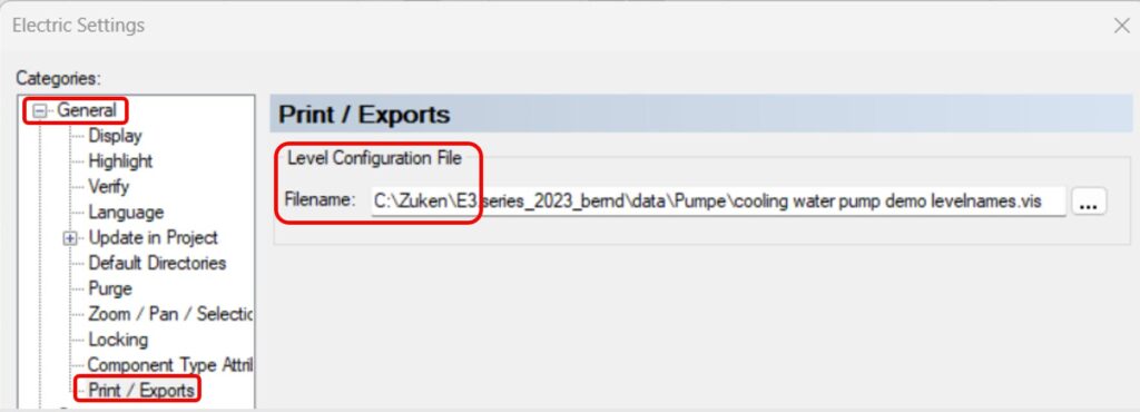
PDF EXPORTS WITH LEVEL HANDLING
A new visibility management feature in E³.series significantly enhances user efficiency by automatically handling schematic levels during PDF export. Previously, users had to manually switch off levels, which could lead to oversights and errors in the final documentation. Now, with the automatic visibility management setting, the correct levels are applied seamlessly during export, and they revert to their original state once the process is complete. This not only saves time but also ensures that the final output is consistently accurate and professional, allowing users to focus on design without worrying about manual adjustments.
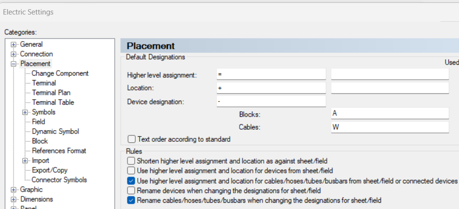
ENHANCED LOCATION DESIGNATION INHERITANCE
In response to numerous customer requests, E³.series 2025 now offers enhanced functionality for inheriting higher-level assignments of location designations.
This feature, previously available only for standard electrical components, now includes cables, bus bars, hoses, and tubes. Users can choose between the existing behavior and the new behavior by adjusting the settings, while the rest of the process remains the same as for other devices.
ATTRIBUTE DIPLAY FOR HIERARCHICAL DEVICES
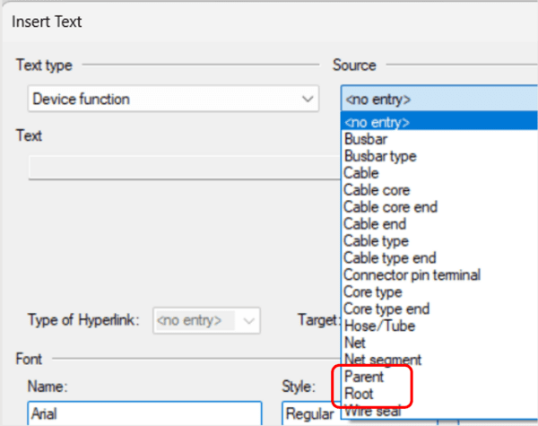
Attributes of hierarchical devices, such as multi-level assemblies, connectors with inserts, or terminal blocks, can now be displayed directly within text notes. With the addition of ‘Parent’ and ‘Root’ options in the source item menu, users can easily access and display the necessary information, streamlining their workflow and improving accuracy when working with complex, hierarchical designs. This eliminates the need for manual copying and pasting of attribute information from other levels, such as parent or root.
NEW ”MATING CONNECTOR GROUP” FEATURE
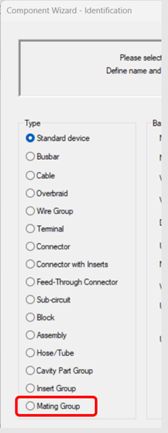
With the mating connector group feature, you can manage multiple mating connectors as a group, just like how pin terminal groups are handled. The method of defining this group is identical to the process already used for pin terminals. When creating a new component in the database editor, a new component object called “Mating Group” is available. This allows you to centralize the definition of mating connectors within the library. Any changes to the mating group—such as adding or removing connectors—are automatically applied to all components using the group. This not only streamlines connector management but also reduces the time and effort required for maintaining connector relationships in complex designs. Previously, when managing connectors, each mating connector had to be defined individually.
ENHANCED PIN CONTROL OF EQUIVALENT PINS
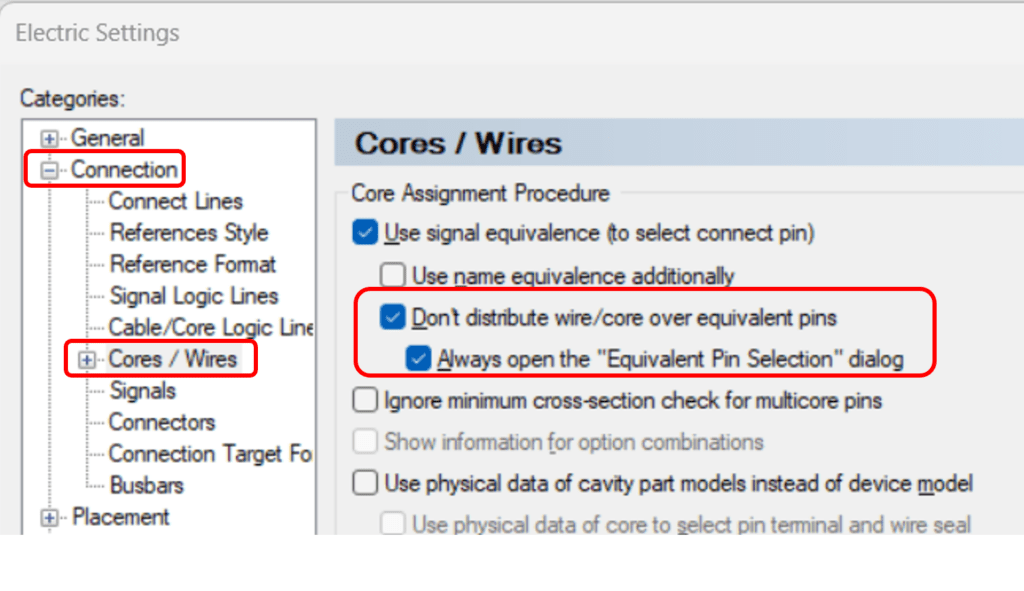
With this new feature, E³.series introduces a way to ensure that the connection to an equivalent pin can be controlled and fixed in the schematic itself, rather than relying solely on the software to determine the optimal connection during panel routing.
This allows designers to have greater predictability and consistency in their designs, ensuring that the correct pin assignment is maintained throughout the process, even in scenarios where panel routing is not involved. Consequently, this feature addresses the previous issue of inconsistent pin assignments in reports.
INTUITIVE ANGULAR DIMENSIONING
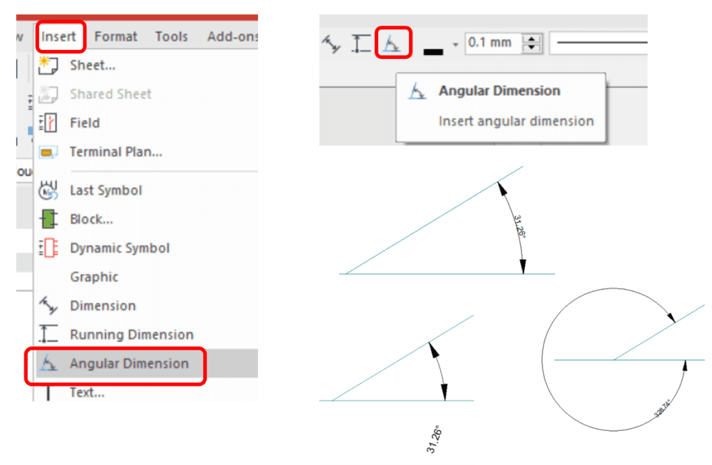
This new feature allows users to create angular dimensions for angled objects. When measuring, you can select two objects, such as connect lines on a form board or other graphics, and then draw an angular dimension. Depending on how you move the mouse, either the inner or outer circle will be dimensioned. The text can be placed freely, and the rest of the behavior follows the existing functionality for standard dimensions, making it intuitive and consistent with previous measuring tools in the software.
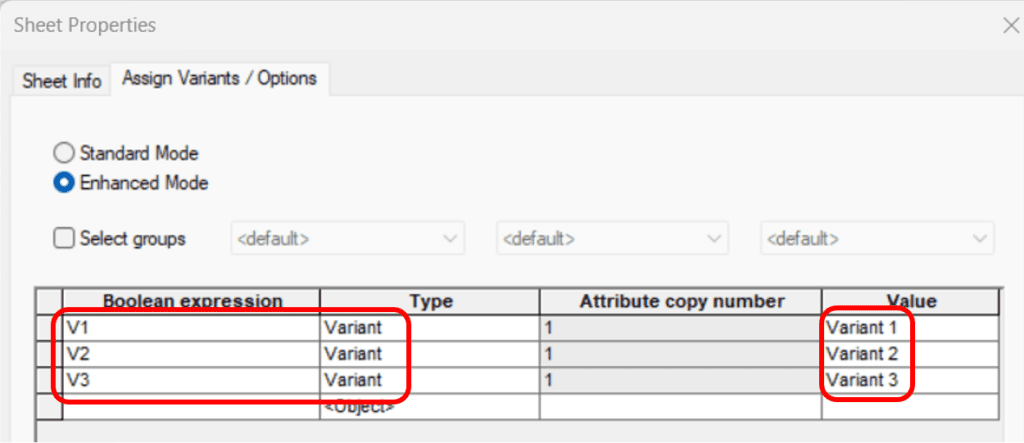
DYNAMIC VARIANT-SPECIFIC SHEET TEXTS
This new feature in E³.series enhances variant handling by extending it to sheet texts that represent sheet attributes. Now, users can assign sheet attributes to specific variants, allowing the corresponding sheet text to dynamically change based on the selected variant. This means that sheet attributes can be customized and displayed differently depending on the variant in use, providing greater flexibility and accuracy in documentation and design outputs when working with multiple variants. This improvement streamlines the management of variant-specific information, ensuring that the correct data is always shown on the appropriate sheet.
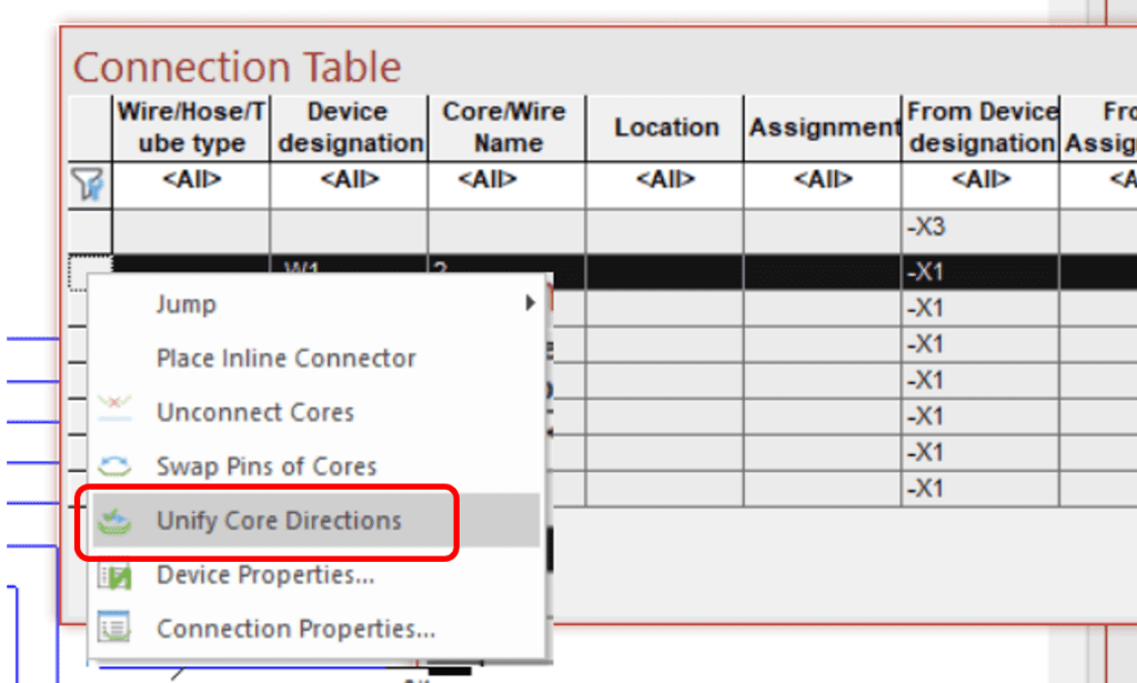
CONSISTENT ”FROM-TO” CABLE DIRECTION
This new feature ensures consistent “from-to” information when laying new cores in a cable. You can now define that all subsequent connections follow the direction of the first existing line. This ensures that all new connections maintain consistent “from-to” information, even if the graphical layout varies.
Additionally, this feature can also be applied to existing wirings where there may be mismatches in direction. You can now align and unify the core directions in the connection table, ensuring consistency throughout the design. This predefined directionality in the schematic eliminates the need for recalculations during report generation, saving time and ensuring accuracy.
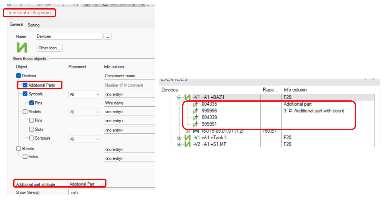
SHOW ADDITIONAL PARTS IN DEVICE TREE
This new feature enhances the management and visibility of additional parts in the bill of materials (BOM). Users can define an attribute for additional parts, with “additional part” as the default attribute. This makes additional parts directly visible under the respective device in the tree, marked with a plus sign icon. The information displayed includes the part number, quantity, and any associated comments, following a specific format: part number, quantity, and comments at the end.
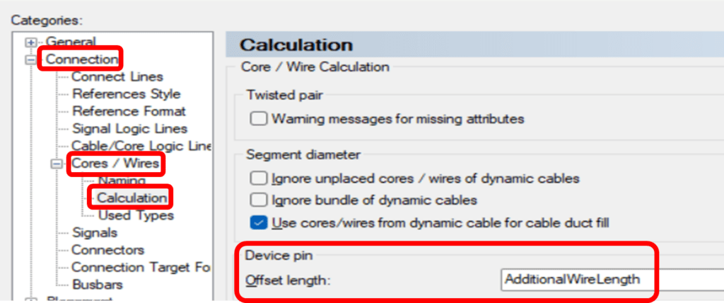
AUTOMATIC INTERNAL WIRE LENGHT CALCULATION IN E³.FORMBOARD
A new feature in E³.formboard enables the automatic calculation of the internal wire lengths inside connectors, eliminating the need for users to manually create scripts to account for this additional wire length. In release 2025, there is an option to define this internal length as an attribute. This attribute is customizable and not fixed, allowing for flexibility. When defined, the additional length is considered in the length calculations of E³. The internal lengths can also be displayed as separate columns in the connection table, where they can be modified, edited, or deleted.
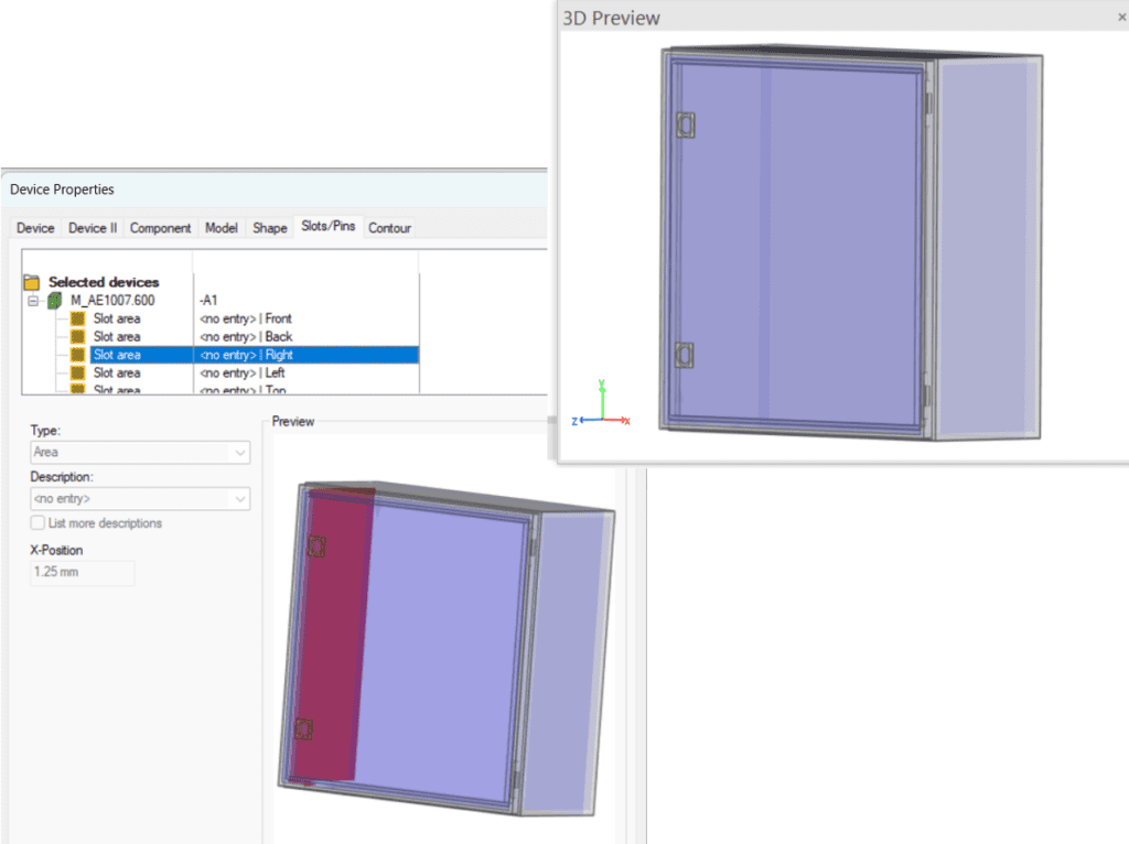
TRANSPARENT 3D MOUNTING SLOT VISUALIZATION IN E³.PANEL
The 3D representation of mounting slots in E³.panel, first introduced in the 2022 version, has been enhanced to display in transparent mode. This improvement allows users to clearly see the specific area and direction they are working within the cabinet layout. By providing a more intuitive view of mounting slots, this feature simplifies the placement of components and improves overall accuracy, ensuring a smoother and more efficient design process.
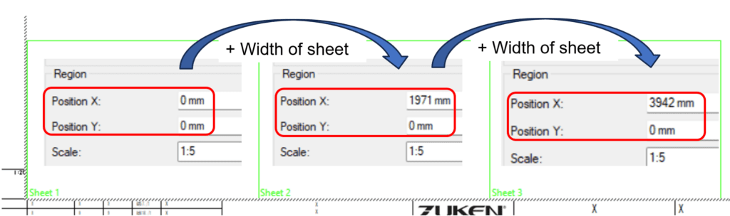
AUTOMATIC PANEL SHEET POSITIONING
Managing multiple panel sheets in E³.series has become significantly more streamlined. Previously, when adding new panel sheets, users had to manually adjust the coordinates to avoid overlap, as all sheets would default to the origin (0,0). Now, with automatic panel sheet positioning, new sheets are automatically placed with the correct offsets relative to existing ones, eliminating the need for manual adjustments. While the automatic positioning is set to optimal placement, users still have the flexibility to edit these values if needed for custom layouts.
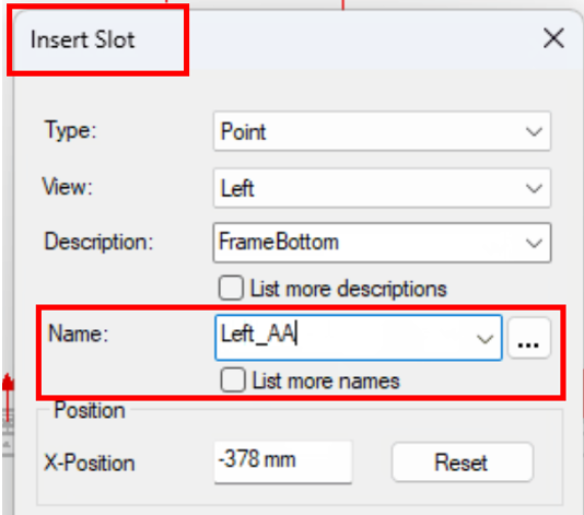
CUSTOM SLOT NAMING FOR ENHANCED ORGANIZATION OF COMPLEX CABINET DESIGNS
As cabinet designs grow more complex with dynamic configurations, managing mounting slots in E³.panel has been enhanced for better clarity and organization. Previously, slots were automatically assigned generic names (e.g., area slot, line slot, or punctual slot), making it difficult to distinguish between them in intricate designs. Now, users can define custom names for each slot, allowing for easier identification and organization throughout the design process. The naming is entirely flexible and tailored to your needs.
While the custom name helps differentiate slots in your list, it doesn’t affect functionality. The system still checks the slot description to determine whether components can be placed. This new feature adds an extra layer of clarity in managing complex cabinet layouts without altering existing placement rules.
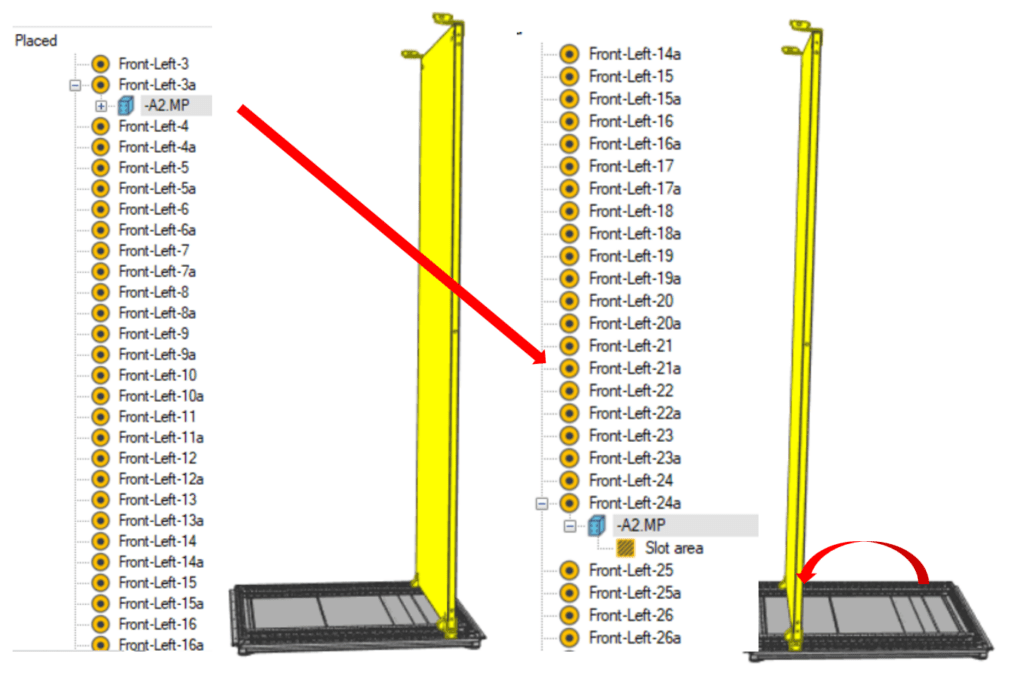
PANEL SLOT PLACEMENT VI THE DEVICE TREE
In E³.panel slots—whether named or unnamed—can now be directly used in the device tree for placing or moving elements, offering a more intuitive alternative to working in 2D or 3D drawings. This new functionality simplifies the process of positioning components by allowing users to drag and drop elements onto slots within the tree, where precision may be easier to achieve than in traditional graphical views. To ensure that the orientation of the element is preserved during placement, simply hold the Shift key during any drag-and-drop operation.
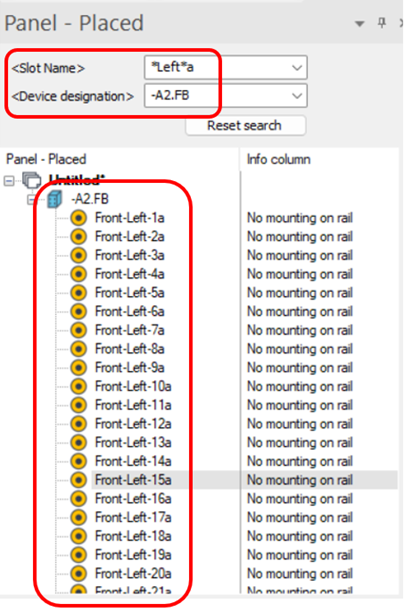
EFFICIENT SLOT MANAGEMENT WITH TREE FILTERING
In complex cabinet designs with numerous slots, navigating through long lists can become cumbersome, even when the slots are named. To streamline this process, E³.panel introduces a powerful search and filter function within the device tree. This feature allows users to filter and search for slots based on criteria such as device name, slot description, or other attributes. The result is a condensed view, showing only the relevant slots that match the filter criteria, making it easier to manage and place components without scrolling through large lists.
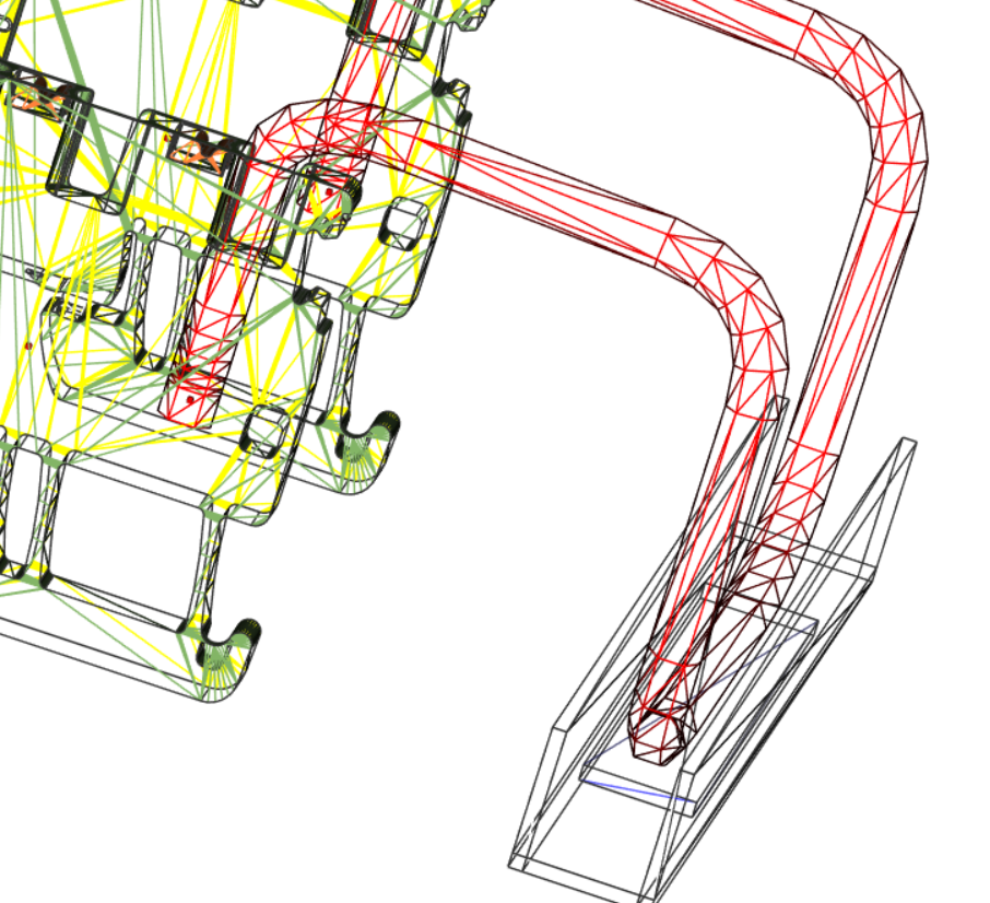
PRECISION WIRE ROUTING WITH 3D COORDINATES AND OFFSETS
E³.panel now offers enhanced precision in wire routing by incorporating detailed 3D coordinates and offsets within components. Inside each component, the XYZ coordinate of the pin is precisely defined, along with the exact offset where the wire starts. At this point, the wire length is zero, and from there, the length is calculated as it follows the defined routing path. This improvement brings a higher level of accuracy to wire length calculations, as it accounts for the true physical placement of wires in 3D space. As designs increasingly move toward 3D representation, this feature ensures that wire routing is more precise than ever before, supporting more complex and realistic designs.
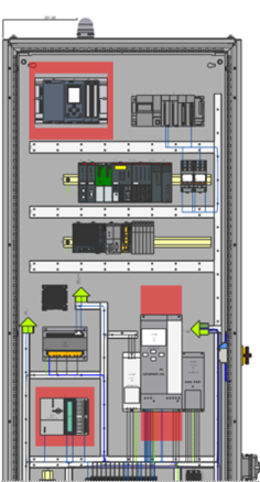
ENHANCED 2D REPRESENTATION BASED ON 3D VIEWS
Despite the shift toward 3D design, most users still rely on 2D views for documentation purposes, such as panel layouts, printouts, and measurements. Traditional 2D representations have limitations, especially when elements overlap, making it difficult to determine which should be displayed on top. In contrast, 3D views provide a more accurate representation, but until now, providing that clarity in a 2D representation has been challenging. The new feature in E³.panel offers a 2D representation based on the 3D view, delivering a more realistic depiction of the design. It eliminates the issue of deciding which element appears on top, as the 3D perspective inherently resolves that.
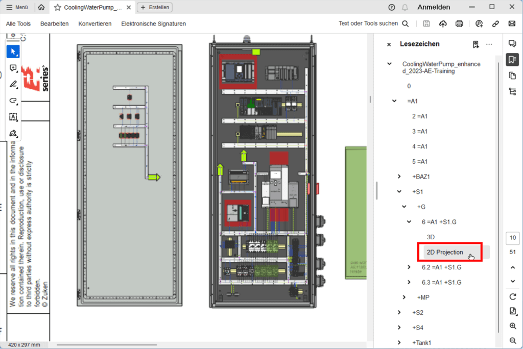
ENHANCED PDF EXPORT: 2D AND 3D VIEWS IN THE SAME EXPORT
E³.panel now offers enhanced PDF export functionality, allowing users to include both 2D projections and 3D representations in their PDFs. Previously, users could export either the traditional 2D sheet or the 3D representation with a simple checkbox option. Now, with the addition of a new checkbox, users can export both the 2D projection and the 3D view within the same PDF. This provides greater flexibility by allowing viewers to interact with the 3D model (e.g., rotate and move it) while also accessing the 2D projection for detailed documentation. Users can choose to export either the 2D projection, the 3D representation, or both, offering a customizable export process. Furthermore, this feature can be utilized in non-E³ documents, expanding its utility beyond the E³.series environment
ENHANCED SLOT DEFINITION FOR COMPLEX GEOMETRIES
E³.panel now allows for the creation of complex slot geometries beyond the traditional rectangle, accommodating the increasing complexity of modern designs. Users can now define any shape as a polygon, giving greater flexibility in slot design. The process is intuitive: start with a basic rectangle, then edit the points by moving or deleting them to refine the shape into a custom polygon that better represents the physical layout requirements. This new capability mirrors the behavior of other editable elements in E³.series, enabling users to precisely define and modify areas to match real-world examples.
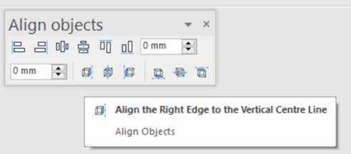
ALIGNING ELEMENTS ON BASE OBJECTS
E³.series 2025 expands the alignment capability by allowing users to align elements to base objects, such as doors, with new icons enabling precise alignment to the right, middle, or left sides, as well as top, center, or bottom positions. Whether aligning elements horizontally or vertically, this new functionality ensures more accurate and organized placement, particularly in scenarios involving doors or central lines in panels.
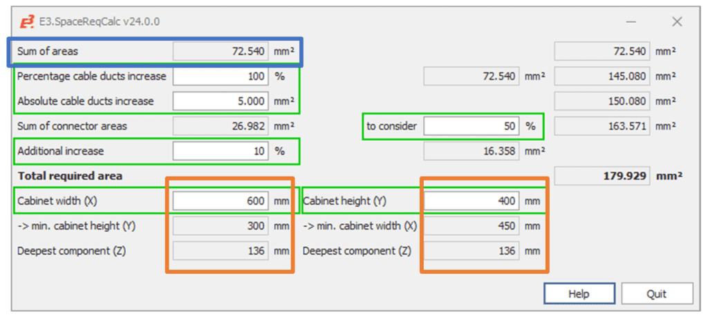
NEW CABINET SPACE REQUIREMENT CALCULATION TOOL
This tool is designed to help users determine the necessary space for unplaced panel elements, assisting in the selection of the right rack or cabinet size. It automatically calculates the space requirements, excluding already placed elements, and allows for adjustments based on experience, such as additional space for cable ducts or other components.
Users can customize various parameters, like adding percentages to account for additional requirements, resulting in a calculated output that fits the specific project needs. Additionally, the tool can accommodate predefined cabinet widths and calculate the minimum height and depth needed for optimal cabinet selection. This provides users with an efficient way to choose the best fitting cabinet from.
NEW COOLING CALCULATION TOOL
A new Cooling Calculation tool in E³.panel helps users assess the cooling requirements for elements within a cabinet. Many components generate power loss, which contributes to heat buildup. By defining the power loss in the library, users can calculate the total heat load of their layout. For elements not predefined in the library, additional fields allow for manual input.
The tool also factors in real-world conditions, such as simultaneous activity of components (e.g., assuming 60% active at once) and the enclosure’s environment—whether it stands freely or is placed side by side with others. The result is an accurate calculation of the cooling capacity needed to maintain an optimal internal temperature. All calculations follow IEC and DIN standards, ensuring compliance with industry norms (IEC 60 89 and DIN 57 600).
EXPANDED API CAPABILITIES
E³.series 2025 introduces 100 new and enhanced COM calls in its API, providing expanded functionality for developers. These new features are thoroughly documented in the API documentation, with a dedicated section outlining what’s new in the 2025 release. The documentation organizes these updates into categories such as the E³ database and multi-user administration, allowing users to easily see what’s new, changed, or duplicated. Despite the comprehensive documentation, this new set of COM calls offers significant opportunities for custom automation and integration.
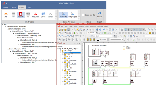
NEXT-GENERATION PLC BRIDGE WITH EXPANDED FUNCTIONALITY
E³.series 2025 introduces the next generation of the E³.PLCBridge, now fully AML-based, eliminating the need for specific formats. This updated PLC Bridge supports both import and export of topology, including manufacturer-specific topologies, and also accommodates multi-bus systems.
The new PLC Bridge comes with an internal editor that allows users to modify elements, texts, and addresses directly within the tool, with changes automatically reflected in E³.series. This integrated approach eliminates the need for external editors like Excel, streamlining the workflow and enhancing efficiency. Users of the previous version are encouraged to upgrade to take advantage of the new features and improved functionality.